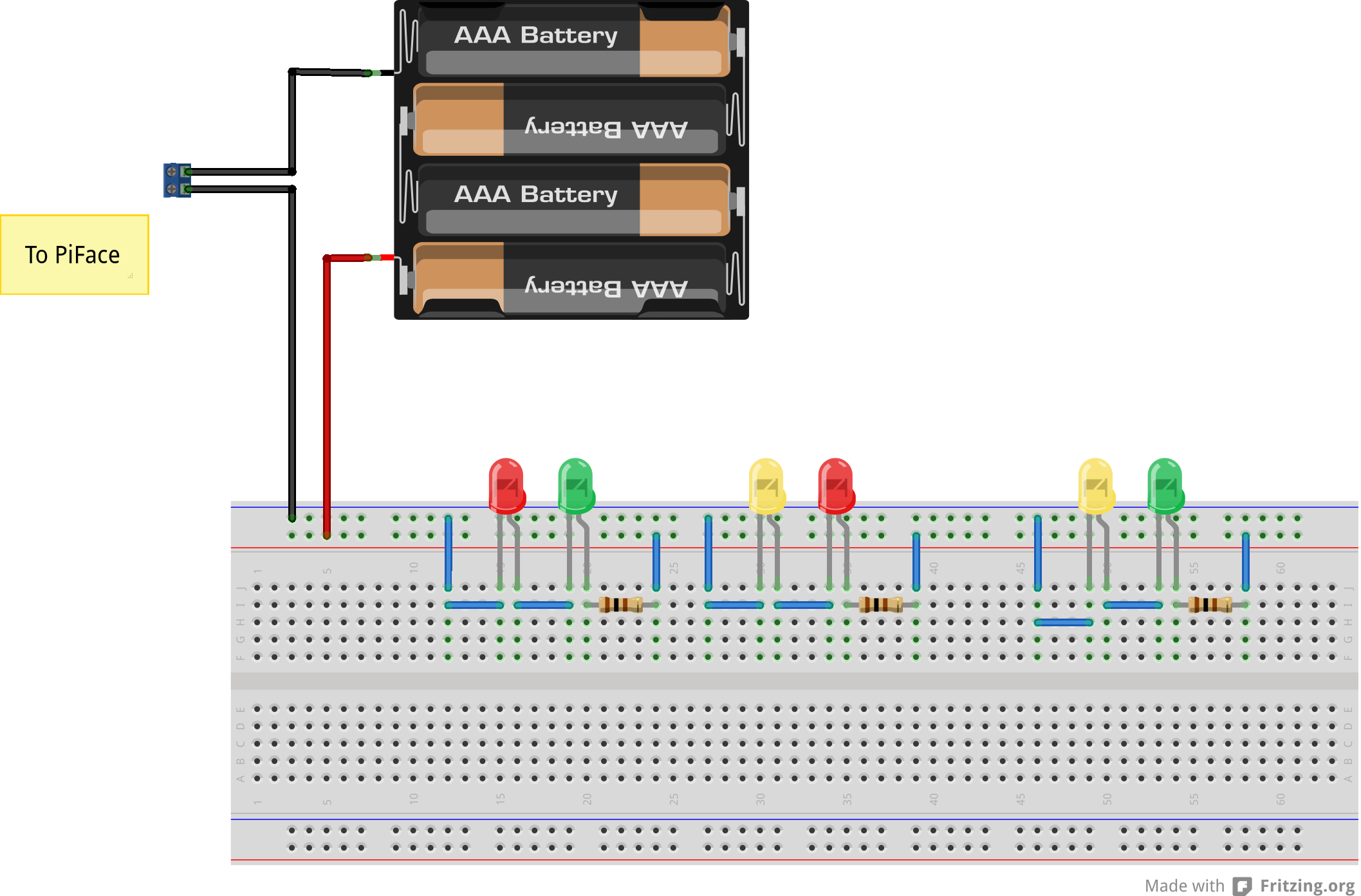
Piface Wiring Diagram
Each relay is connected to three black screw terminals. Adding a magnetic contact sensor prerequisites the working of magnetic contact sensors.

Raspberry Pi + PiFace Digital automatically detects loss
This tutorial describes the full install process of leosac on raspbian.
Piface wiring diagram. Slide a cr1220 battery into the battery holder with the positive side (flat side marked with a +) facing upwards, in the direction indicated by the red arrow in the image below. Home electronics can open up a new dimension in home automation especially when used with an arduino or raspberry pi.there is however a very real danger when using mains electricity, including risk of electricution and danger of electrical. The receiver wiring diagram logging detection data summary 6.
I have my new raspberry pi and piface card. Diagram of piface wired for touch inputs Doorgaan naar hoofdcontent adventures of a tech fun, coding, making, electronics, notes, design, opinions zoeken.
Sun nov 11, 2018 5:01 pm. You can try touching the ground wire directly to the input terminal to check it is registered and then work methodically along the wires to check there is a good connection. Hi, super beginner here when it comes to hardware.
My daughter's 7th grade project, a pet auto feeder. This board supports 8 digital inputs, 8 digital outputs (open collector) of which two are equipped with relays capable of switching 5a/20v (the relays themselves have a higher rating but the circuit board and screw terminals do not). Welcome to piface control and display (cad)'s documentation!¶ the pifacecad python module provides functions and classes for interacting with piface control and display.
Route the mains power to the gateway router's wall wart through one of the two relays on the piface digital (see diagram below) wiring the ac mains for powering the gateway router through one of the relays of piface create a file that contains the script to ping and check if the internet connection on the gateway is working. Fitting on the raspberry pi with the battery towards the centre of the raspberry pi, align the piface real time clock's holes over the raspberry pi's gpio pins. It is designed for use with c and rtb (basic) on the raspberry pi only.
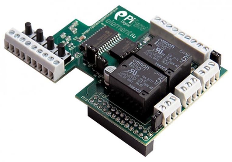
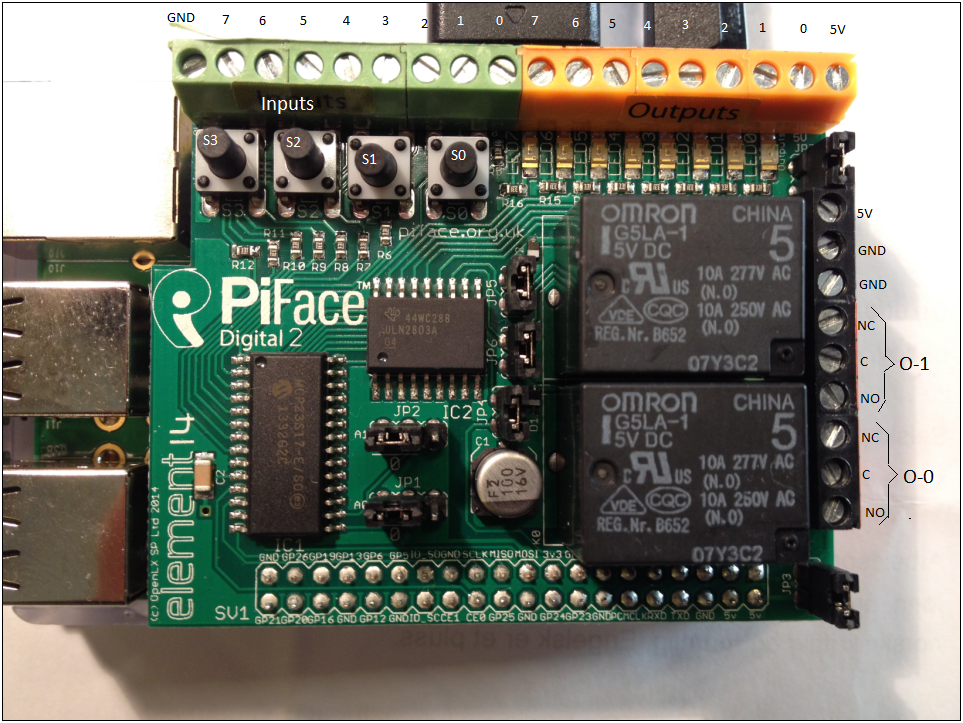
Piface™ digital 2 has two changeover relays in parallel with the first two outputs. The source code is not publicly available but may be made available to those who wish commercial support. If no input is registered then check your wiring.
The basic wiring diagram is shown below in figure 2. I thought it would be the easiest way to attach some simple servos to the raspberry You can use the 2 buffered outputs in parallel with the relays, but they will obviously click on/off when you use them.
Support for the piface i/o board is available in release 1045 and onwards. It fits *over* the gpio pins, leaving them ready for use with all your other raspberry pi accessories. Due to the low resistance windings used in stepper motors, care must be taken to make sure that the current delivered to the board does not exceed 2a.
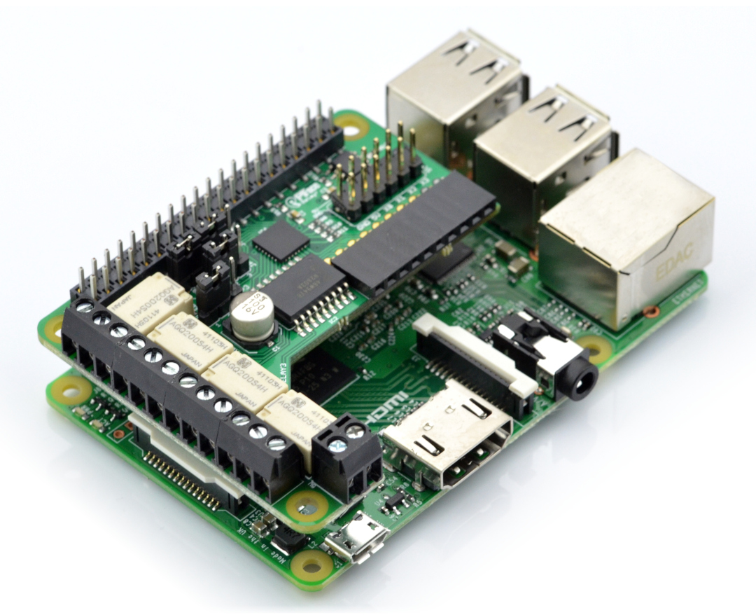
Piface digital i/o expansion board gertboard summary 4. Zoeken in deze blog raspberry pi, pyface digital, the lost documentation, i found it finally augustus 22, 2013 Raspberry pi, piface digital, schematic.
Adding cameras to our security system prerequisites the raspberry pi camera module A stepper motor mounted directly to the pillbox which spins the lid controlled by a rapberry pi with a piface io extension board. 2 of the output connections are connected to mechanical relays.
In reality, some car batteries perform much better than others, depending on the vehic. Wiringpi is a pin based gpio access library written in c for the bcm2835, bcm2836 and bcm2837 soc devices used in all raspberry pi. The pins' functions are shown in the diagram below and are labelled on the underside of the piface™ digital 2.
It will walk you through a complete install on a raspbian system. Describe the installation process when using a raspberry pi + piface board + wiegand reader. Help needed with wiring on piface former member over 8 years ago hi does anyone know how or if it would be possible to wire the diagram attatched so it can be contolled via piface im totally cack at electronics so any help would be much appreciated.
The emulator will register this by showing a dot on the corresponding input.
Controlled Lights Next Project

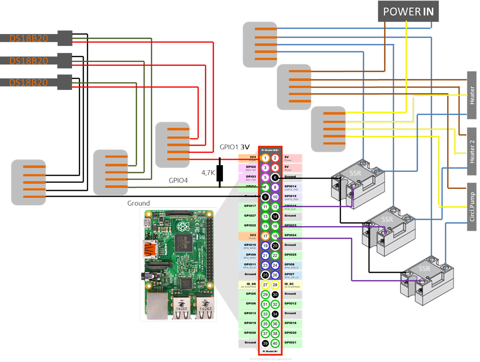
[VR_0993] Raspberry Pi Wiringpi Relay Wiring Diagram
CraftBeerPi
The Trouble with PiFace Pieces of Pi

Wiegand Wiring Diagram Complete Wiring Schemas
Wiring up a PIR to a PiFace Digital2 element14


A Slice of Raspberry Pi Finalizing the design of the
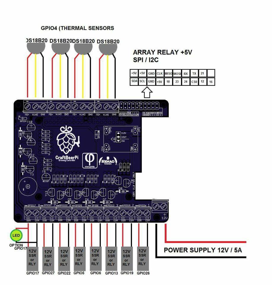
CraftBeerPi
Wiegand Wiring Diagram Complete Wiring Schemas

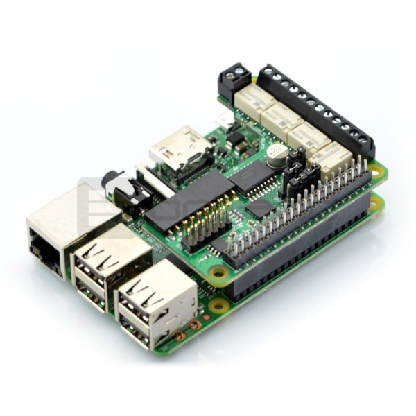
PiFace Relay+ rozszerzenie do Raspberry Pi 2/B+ Sklep
PiFace Relay+ rozszerzenie do Raspberry Pi 2/B+ Sklep
MultiClassification Face Recognition on Raspberry Pi B+

Interfacing an I2C GPIO expander (MCP23017) to the

TriviaBox Trivia Game for RaspberryPi
PiFace PiFace Digital

Shift Register 74x595 Wiring Pi

PiFace Wiring Pi

RPi, PiFace Digital 2
Automated brewery Leaning Man Brewery
